This is my 60 second guide to wiring a BT (UK) phone line into a home network using Cat5e cabling, based on my own recent experience. This should allow you to plug your phone into any available RJ45 socket, then at your patch panel connect it into your phone line directly from the corresponding port.
1. BT Cable to Master Socket
The BT cable comes into the house from somewhere outside and is terminated on a 'master' socket. The cable contains 4 - 6 wires, but usually just 4. Only 3 off these are officially used, and only 2 are actually required. The 3rd (Orange/White?) wire is the bell wire, only used to make older phones ring, but not required by modern phones and can cause interference to ADSL if connected. I think you are still supposed to connect the bell wire from the BT cable to the master socket, but then you don't have to extend it to any extensions (I just left it out completely).
The two remaining wires are the 'A' (White, 0V, Pin 2) wire and the 'B' (Orange, -50V to Earth, Pin 5) wire. Terminate these on the master socket on the corresponding contacts.
2. Extension Socket
I used a length of Cat5e cable (better for carrying ADSL as less interference due to twisted pairs) to run a single slave extension from the master socket to a box near my patch panel. NB. There are only two wires required to carry the phone signal, extending the two wires from the BT master socket.
At the master socket end, I terminated the cable onto the back of the removable faceplate.
Blue -> Pin 2
Blue with White Stripes -> Pin 5
At the patch panel end, I terminated the cable onto an ADSL face plate - this basically has an ADSL filter built in, removing the need for untidy dongles hanging off the socket front. The face plate provides two sockets - a BT plug socket (filtered) and an RJ11 (unfiltered) socket for ADSL to connect to the router.
As previously, terminate the wires as follows:
Blue -> Pin 2
Blue with White Stripes -> Pin 5
Test this works for ADSL and your phone line before proceeding any further!
3. Make your patch cables!
BT -> RJ45: To connect your extension socket to a port in your patch panel. I don't have the expensive crimping tool for BT plugs, so I simply used an old BT cable, snipped off one end and attatched an RJ45 plug instead. Quality of cable not really an issue as only analog voice signal is being carried on this cable - ADSL has already been separated out.
A BT plug has 4 pins - only the outer two pins (1 and 4) are required. The color of the wires inside the cable may vary, but I used the red and white wires. The important thing is that Pins 1 and 4 on the BT plug are connected to Pins 3 and 6 on the RJ45 plug (if in doubt use a multimeter with continuity testing to test and confirm after you've made the cable).
BT Plug end:
White -> Pin 1
Red -> Pin 4
RJ45 end:
Red -> Pin 3 (to line up with a narrower RJ11 plug's pins 1 or 2)
White -> Pin 6 (to line up with a narrower RJ11 plug's pins 4 or 5)
RJ45 - RJ11: To connect your telephone to an RJ45 wall socket. NB. You can actually put an RJ11 plug into an RJ45 socket (they are the same height and depth just different widths), so you could also get away with an RJ11 -> RJ11 cable. I used a length of Cat5e for the actual cable to minimise any impact on the ADSL signal.
RJ11 end: Assuming a '4 pin' RJ11 plug (they can have up to six):
Blue -> Pin 1 (Pin 2 on a 6 pin RJ11 plug)
Blue with White Stripes -> Pin 4 (Pin 5 on a 6 pin RJ11 plug)
RJ45 end:
Blue -> Pin 3 (to line up with a narrower RJ11 plug's pins 1 or 2)
Blue with White Stripes -> Pin 6 (to line up with a narrower RJ11 plug's pins 4 or 5)
RJ11 - RJ11: To connect the ADSL socket of the extension face plate to the ADSL router. I used a length of Cat5e for the actual cable to minimise any impact on the ADSL signal.
Assuming a '4 pin' RJ11 plug, for both plugs:
Blue -> Pin 1
Blue with White Stripes -> Pin 4
NB. If using an existing RJ11 to RJ11 cable, make sure it is 'straight through', i.e. that each pin on each plug is connected to the same pin on the plug at the opposite end. At a minimum, pins 1 and 4 should be connected this way.
Good luck!
Tuesday, 12 July 2011

Tuesday, 10 May 2011
How to Extract the Contents of an MSI file
To extract the contents of an MSI installer file, you can us ethe Windows msiexec command line utility.
msiexec /a "path to MSI file/msi filename"
A wizard will run and you'll be prompted where to save the extracted files.
msiexec /a "path to MSI file/msi filename"
A wizard will run and you'll be prompted where to save the extracted files.
Tuesday, 15 March 2011
Debugging MSI installer errors
Some notes on debugging MSI installer errors.
Run the MSI using this command:
msiexec /i "" /l*vx "C:\logname.log"
Run the MSI until the error occurs, then browse through the resultant log. Some common errors include:
DEBUG: Error 2826: Control Line1 on dialog FatalErrorForm extends beyond the boundaries of the dialog to the right by x pixels
You can ignore this one. It's simply telling you that a control on the dialog exceeds the boundaries of that dialog box by x pixels.
From what I've read, the trick to reading installer logs is to search from the top for the text string "Return value 3", then look at the lines immediately preceeding the occurence.
Entries with errors begin with the string "ERROR :" in the logs.
Run the MSI using this command:
msiexec /i "
Run the MSI until the error occurs, then browse through the resultant log. Some common errors include:
DEBUG: Error 2826: Control Line1 on dialog FatalErrorForm extends beyond the boundaries of the dialog to the right by x pixels
You can ignore this one. It's simply telling you that a control on the dialog exceeds the boundaries of that dialog box by x pixels.
From what I've read, the trick to reading installer logs is to search from the top for the text string "Return value 3", then look at the lines immediately preceeding the occurence.
Entries with errors begin with the string "ERROR :" in the logs.
Wednesday, 22 December 2010
Using wildcards for searching and replacing in Microsoft Word 2007
I needed to clean up the output from a csvde query by removing the DN from the results. The DN was in the format "CN=...,OU=...,DC=...,DC=...",other data.
To remove only the DN from each line and leave the other data, I pasted the results into Microsoft Word 2007, then opened the 'Replace' dialog. I then clicked on the 'More' button at the bottom left which revealed additional options, including one called 'Use Wildcards'. I put a check against this option, then did a search for "*", to replace with nothing. This immediately cleared up all of my query results, leaving only the other data which I needed.
More information on using wildcards in the Word Find and Replace here: http://www.gmayor.com/replace_using_wildcards.htm
To remove only the DN from each line and leave the other data, I pasted the results into Microsoft Word 2007, then opened the 'Replace' dialog. I then clicked on the 'More' button at the bottom left which revealed additional options, including one called 'Use Wildcards'. I put a check against this option, then did a search for "*", to replace with nothing. This immediately cleared up all of my query results, leaving only the other data which I needed.
More information on using wildcards in the Word Find and Replace here: http://www.gmayor.com/replace_using_wildcards.htm
Wednesday, 13 October 2010
Searching for and replacing carriage returns (paragraph breaks) with line breaks in Microsoft Word
A useful tip I picked up today - you can search for carriage returns (paragraph breaks) and line breaks in Microsoft word by using the carat character (^) followed by 'p' or 'l' for paragraph or line as required.
e.g.
^p
^l
On several occasions I've pasted text into Word and hidden carriage returns in the text cause Word to display more spacing between the lines than a normal line break. Doing a simple find and replace using the above characters saves a lot of manual corrections!
e.g.
^p
^l
On several occasions I've pasted text into Word and hidden carriage returns in the text cause Word to display more spacing between the lines than a normal line break. Doing a simple find and replace using the above characters saves a lot of manual corrections!
Thursday, 2 September 2010
Fixing the trigger sensitivity of a CME GPP-3 USB MIDI Pedal
A few years ago I purchased a CME GPP-3 USB Grand Piano Style MIDI Pedal to use with my Fatar Studio 900 MIDI keyboard controller. I believe it was (and still is) fairly unique in being modelled very closely on real piano pedals in both look and feel, and is a really useful addition to any studio set-up. I've used mine extensively since I bought it, both live and during recording, and I'd recommend it to anyone used to playing a real piano. I think the Chinese manufacturer (CME) has discontinued it, but you can still find it on eBay!
When I first got it however, I discovered an issue with the trigger sensitivity of the 1st (sustain) pedal. As the screenshot below (taken from Cockos Reaper) shows, the pedal trigger sends a MIDI CC67 value from 0 to 127 as it is pressed down, (CC67=127 when the pedal is fully depressed). The problem was that when the pedal was fully released, the CC67 value was ALSO 127! On further investigation, I found that when fully released, the pedal was not even touching the trigger sensor inside the unit, and as it began to be pressed down it would then touch the sensor and generate CC67 values from 0 to 127, until the pedal was fully depressed. In practical terms, this meant that any MIDI device I was controlling with the pedals would think the sustain pedal was fully depressed when it actually WAS fully depressed, but ALSO when it was fully released. When I wanted the pedal to be 'released' I had to keep the pedal pressed slightly down (i.e. NOT fully released) to ensure that the trigger sensor was being touched and therefore to generate a very low CC67 value, representing a released sustain pedal. The irony was that if I did physically fully release the pedal, it would then send a CC67 value of 127, telling any attached MIDI devices that the pedal was in fact fully depressed again, the complete opposite of what it actually was!
This may have been a problem only on my particular unit, but in case any fellow GPP-3 owners are experiencing the same issue, I've posted some photos and an explanation of my quick and simple D.I.Y. solution below:
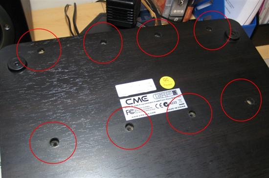
1. Flip the unit over and remove the 8 screws from the wooden base (you'll need a Phillips cross-head screwdriver):
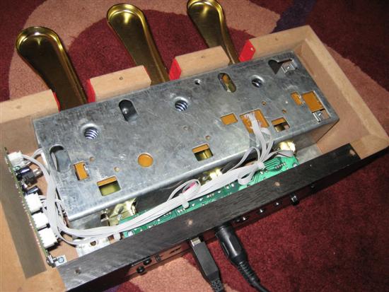
2. Remove the wooden base. The pedals are attached to a metal casing inside the frame. You'll need to remove some more screws then the whole pedal unit should come free:
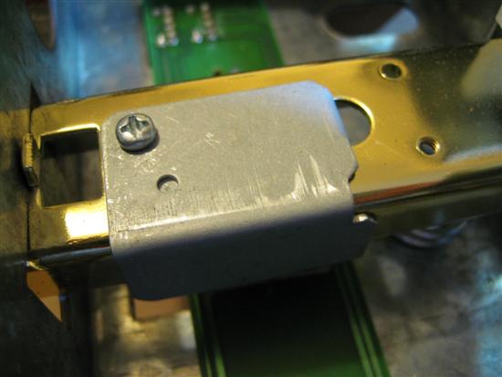
3. Flip over the detached metal casing and find the problem pedal. There should be a metal bracket (as shown below) which presses down onto the trigger sensor on the PCB underneath. Unscrew the bracket:
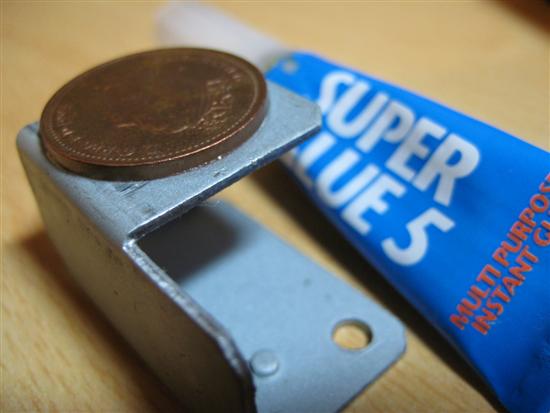
4. Using some superglue, stick a British penny coin (or your local currency equivalent) on the underside of the metal bracket, and allow a few minutes for it to dry:
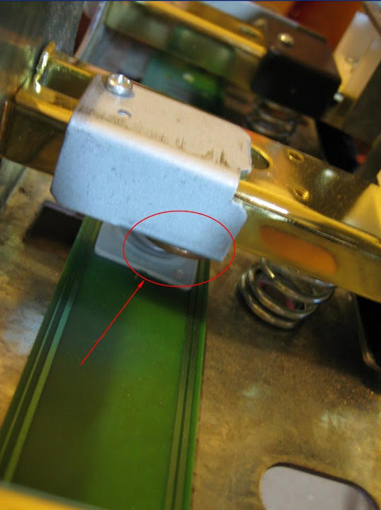
5. Reattach the metal bracket to the pedal you removed it from. The added depth of the penny coin should be enough to press lightly on the trigger sensor and prevent it from being fully released when the pedal is not being pressed:
.JPG)
6. Reattach the metal frame to the wooden casing, and then screw the base back on. Test your unit, and you should find it works as intended!
Link to the GPP-3 on the manufacturer's website:
http://www.cme-pro.com/en/product-detail.php?product_id=34
When I first got it however, I discovered an issue with the trigger sensitivity of the 1st (sustain) pedal. As the screenshot below (taken from Cockos Reaper) shows, the pedal trigger sends a MIDI CC67 value from 0 to 127 as it is pressed down, (CC67=127 when the pedal is fully depressed). The problem was that when the pedal was fully released, the CC67 value was ALSO 127! On further investigation, I found that when fully released, the pedal was not even touching the trigger sensor inside the unit, and as it began to be pressed down it would then touch the sensor and generate CC67 values from 0 to 127, until the pedal was fully depressed. In practical terms, this meant that any MIDI device I was controlling with the pedals would think the sustain pedal was fully depressed when it actually WAS fully depressed, but ALSO when it was fully released. When I wanted the pedal to be 'released' I had to keep the pedal pressed slightly down (i.e. NOT fully released) to ensure that the trigger sensor was being touched and therefore to generate a very low CC67 value, representing a released sustain pedal. The irony was that if I did physically fully release the pedal, it would then send a CC67 value of 127, telling any attached MIDI devices that the pedal was in fact fully depressed again, the complete opposite of what it actually was!
This may have been a problem only on my particular unit, but in case any fellow GPP-3 owners are experiencing the same issue, I've posted some photos and an explanation of my quick and simple D.I.Y. solution below:
1. Flip the unit over and remove the 8 screws from the wooden base (you'll need a Phillips cross-head screwdriver):
2. Remove the wooden base. The pedals are attached to a metal casing inside the frame. You'll need to remove some more screws then the whole pedal unit should come free:
3. Flip over the detached metal casing and find the problem pedal. There should be a metal bracket (as shown below) which presses down onto the trigger sensor on the PCB underneath. Unscrew the bracket:
4. Using some superglue, stick a British penny coin (or your local currency equivalent) on the underside of the metal bracket, and allow a few minutes for it to dry:
5. Reattach the metal bracket to the pedal you removed it from. The added depth of the penny coin should be enough to press lightly on the trigger sensor and prevent it from being fully released when the pedal is not being pressed:
6. Reattach the metal frame to the wooden casing, and then screw the base back on. Test your unit, and you should find it works as intended!
Link to the GPP-3 on the manufacturer's website:
http://www.cme-pro.com/en/product-detail.php?product_id=34
Subscribe to:
Posts (Atom)